Lab 9: Shadow Mapping
Expected due date: 16-11-2022
Learning Objectives:
Tasks:
Part 1: Scene and Projection Shadows
For this laboratory we require setting up a scene that will combine the
skills that we have learned in Lab 5 (modelling) and Lab 8 (shadows). We
did a bit of trivial modeling in Lab 8 but for this scene we want to
import the teapot texture from the course files and implement it to the
lab 8 scene environment. This will require that we have two shaders, one
for the teapot and one for the ground. Having two shaders requires us to
change what shaders we are talking to in the application layer. This can
be done by following the simple steps shown in the image below:
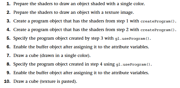
The steps basically are saying that we will use two different programs
that we create at the start of the application and then use the
gl.useProgram() method by sending in the program variable
we want to be communicating with. This requires restructuring of the
code but shader swapping is done in the following pseudo code:
var canvas = document.getElementById("gl-canvas-" + PART_INDICATOR);
var gl = WebGLUtils.setupWebGL(canvas);
if (!gl) { alert("WebGL is NOT available!"); }
var teapotProgram = initShaders(gl, "vertex-shader-teapot-" + PART_INDICATOR, "fragment-shader-teapot-" + PART_INDICATOR);
var groundProgram = initShaders(gl, "vertex-shader-ground-" + PART_INDICATOR, "fragment-shader-ground-" + PART_INDICATOR);
// Global variables
...
function init(){
    // Set up WebGL environment
    ...

     // Load the buffers and get attribute locations
    // ==================== TEAPOT ====================
     gl.useProgram(teapotProgram);
     ...
     // ==================== Ground ====================
     gl.useProgram(groundProgram);
      ...
}

function render(){
    // Setup
    ...
    // ==================== Ground ====================
    gl.useProgram(groundProgram);
    // Write to groundProgram
    ...
    // ==================== TEAPOT ====================
    gl.useProgram(teapotProgram);
    // Write to teapotProgram
    ...
}
With the shaders working for the respective part we can load the model
and the ground data and send it to their respective shader. The creation
of the data is the same as the previous labs but we need to scale and
transform the data for the teapot to get it in the correct spot in the
scene. We can do this either by changing the scale variable when loading
the data from the file, or we can do this using the
modelMatrix part of the MVP matrices. Which I opted for
using the following code in the render method:
var modelMatrix;
modelMatrix = translate(0, prevPosition, 0);
modelMatrix = mult(modelMatrix, translate(0, -1, -3));
modelMatrix = mult(modelMatrix, scalem(0.25, 0.25, 0.25));
We are now satisfying the first two requirements of the lab and can make
the teapot move up and down to make sure that our shadows are really
being projected by the model. This is done by changing the
modelMatrix part of the teapot during our rendering in the
following code:
if (move) {
    if(phi > 2 * Math.PI){
        phi -= 2 * Math.PI;
    }

    phi += moveSpeed;
    prevPosition = MOVE_PEAK * Math.sin(phi);
}
This results in a moving teacup that touches the camera at the top and
touches the ground at the lowest point. Implemented in the same way that
we implemented the moving ball during Part 4 of Lab 1. In a similar
manner we can also move our light position to orbit around the teapot
using the following code in the rendering method:
if (orbit) {
    if (theta > 2 * Math.PI) {
        theta -= 2 * Math.PI;
    }
    theta += orbitSpeed;

    lightPosition[0] = Math.sin(theta);
    lightPosition[2] = -lightRadius + Math.cos(theta);
}
To make sure that the shadow is being projected in the correct position
on the ground we need a better view and thus make an additional camera
that can be toggled on or off that looks at the scene from above. This
is just a conditional camera that checks if the option is turned on to
change the camera using the following code:
var viewMatrix = lookAt(birdsEye ? vec3(0,2.5,-2.99) : eye,at,up)
We have to keep in mind that the near cull point for the perspective
camera is close to the camera when changing the perspective the up
variable in the lookAt method cannot be 3 for everything
would be culled. So the camera has to be as close to 3 as possible. We
can now implement the projection shadows from Lab 8 part 3 to get a
scene with projected shadows on the ground from a 3D model.
Result
Part 2: Shadow Mapping
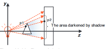
A different approach to shadows that we discussed in the course is
shadow mapping which is ray casting from the light to match what objects
are "visible" in a similar manner that depth testing is done
from the perspective of the camera. This is clearer to understand in the
figure below:
For this technique we also need two shader pairs, one will be
responsible for calculating the distance from the light source to the
objects, and the other will be the one that draws the shadows. Meaning
that if we want to render our previous scene as well we will need a
total of three shader pairs; the teapot shaders, the ground shaders, and
the shadow calculation shaders. The way this technique will work is by
rendering the scene in two versions, one will be a tilted scene replica
tilted in the perspective of the light. Meaning that the eye point
position of the view matrix will be the position of the light source.
The other scene is the normal scene as seen from the desired camera
position. If the former distance is greater draw the fragment in a
darker color. This technique requires two major things in order to work.
The three pairs of shaders and a way to render the two different scenes
simultaneously while not conflicting with each other. To do this we will
be using a FrameBuffer object and call the
frame buffer
to buffer out the shadow calculation plane, unless a flag is raised to
render the scene from the point of the light. Frame buffers are used to
preform types of data processing before the data is displayed. There are
8 steps to using a frame buffer as shown below:
- Create the frame buffer.
- Create texture object for the buffer.
- Create render object for the buffer.
- Bind render object to the target and set rendering size.
- Attach texture object to color attachment of frame buffer.
- Attach render object to the depth attachment of frame buffer.
- Check status of frame object to see if initialization was ok.
- Draw frame (scene) using the frame object.
In code steps 1-7 are shown in the code below:
// Step 1 - Create a framebuffer
framebuffer = gl.createFramebuffer();

// Step 2 - Create a texture object and set its size and parameters
texture = gl.createTexture();
gl.bindTexture(gl.TEXTURE_2D, texture);
gl.texImage2D(gl.TEXTURE_2D, 0, gl.RGBA, SHADOW_SIZE, SHADOW_SIZE, 0gl.RGBA, gl.UNSIGNED_BYTE, null);
gl.texParameteri(gl.TEXTURE_2D, gl.TEXTURE_MIN_FILTER, gl.LINEAR);
gl.texParameteri(gl.TEXTURE_2D, gl.TEXTURE_MAG_FILTER, gl.LINEAR);
framebuffer.texture = texture;

// Step 3 - Create a renderbuffer object and set its size and parameters
depthBuffer = gl.createRenderbuffer();
gl.bindRenderbuffer(gl.RENDERBUFFER, depthBuffer);
gl.renderbufferStorage(gl.RENDERBUFFER, gl.DEPTH_COMPONENT16, SHADOW_SIZE, SHADOW_SIZE);

// Step 4-6 - Attach the texture and the renderbuffer object to the FBO
gl.bindFramebuffer(gl.FRAMEBUFFER, framebuffer);
gl.framebufferTexture2D(gl.FRAMEBUFFER, gl.COLOR_ATTACHMENT0, gl.TEXTURE_2D, texture, 0);
gl.framebufferRenderbuffer(gl.FRAMEBUFFER, gl.DEPTH_ATTACHMENT, gl.RENDERBUFFER, depthBuffer);

// Step 7 - Check if FBO is configured correctly
var e = gl.checkFramebufferStatus(gl.FRAMEBUFFER);
if (e !== gl.FRAMEBUFFER_COMPLETE) {
    console.log('Framebuffer object is incomplete: ' + e.toString());
    return error();
}
We can now use the frame buffer in our render method to draw the scene
in the point of view of the light source. This is done by binding to our
frame buffer again using the line of code
gl.bindFramebuffer(gl.FRAMEBUFFER, frameBuffer). The frame
buffer is acting in the way that is shown in the figure below:
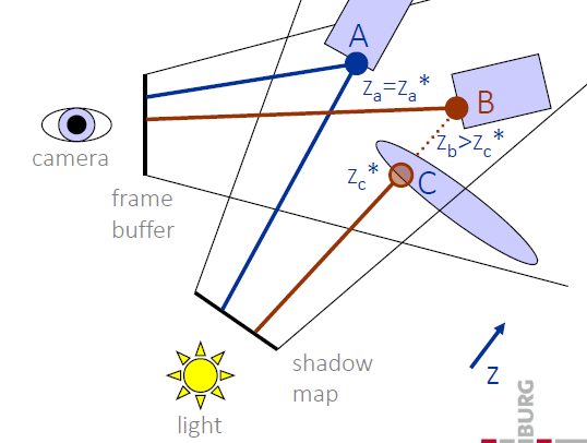
The shaders for this part come from a sample program shown in the course
called Shadow.js which shows this technique in use to
render a shadow of a triangle unto a plane. This part is also created
following the
YouTube tutorial
of shadow mapping.
Result
Part 3: Comparison
When comparing shadow techniques there are multiple aspects that a
developer needs to take into consideration before deciding which to use.
This section will go over what my thoughts are on the comparison.
Projection Shadowing
Projection shadowing is a simple to implement and render technique. An
obvious set back we discovered was that shadows will not follow the
scene and instead float off the plane can be remedied by introducing a
stencil which cuts off the shadow at the edge of the plane. Projection
is inexpensive and even the improved stenciled projection shadow which
simply changes the color of the ground plane is relatively simple to
implement.
However, there is a big limitation on projection shadows as they require
a plane to be rendered on. Meaning that they cannot cast shadows on the
object that projected it, and the object that the shadow is casted on
needs to be a plane. Projection shadowing is not suitable for soft
shadows as the entire shadow object is given the same texture.
Shadow Mapping
In comparison to the projected shadows. Shadow mapping requires more
effort to implement and to render by the computer. Rendering can be
especially tough if the resolution of the shadows is chosen to be large.
This method also can introduce issues such as shadow aliasing and
rendering light sources far away require an expansion to the solution
made here. These two drawbacks can be fixed unlike the drawback for the
projection shadowing although at the cost of more rendering power
needed.
Part 4: Optional Improvement
This part is about improving the shadow mapping as it has aliasing on
the edges and could be improved by implementing a “percentage-closer
filtering”. This part will be completed at a later time due to time
constraints and is not considered a mandatory exercise as part of this
laboratory evaluation.