Learning Objectives:
The purpose of this set of exercises is to investigate the virtual camera and start drawing in 3D. We will work with various methods for setting up the virtual camera and adjust the parameters of the camera. This requires that we define the matrices in the viewing pipeline and concatenate them into a transformation matrix. We will also make different pictures of the scene using various projection methods based on perspective projection and orthographic projection (axonometric views). We do this by drawing a cube using WebGL.
Tasks:
Up until now we have been focusing on drawing 2D objects unto the canvas, which entailed thinking of objects as simple 2-coordinate vectors with a constant z-axis of 0. To transition unto a 3D object model we would require the manual creation and calculation of having the vertex data of the points making up the object. In order to make a simple cube we would require to make a 2D square six times to make the faces of the cube. A 2D cube is made up of two three-vertex-triangles which means that we would have to manually make the vertex data for 12 triangles of 36 vertices, which would look like the following:
var vertices = [
        // Front
        vec3(1.0, 1.0, 1.0),
        vec3(1.0, -1.0, 1.0),
        vec3(-1.0, 1.0, 1.0),
        vec3(-1.0, 1.0, 1.0),
        vec3(1.0, -1.0, 1.0),
        vec3(-1.0, -1.0, 1.0),

        // Left
        vec3(-1.0, 1.0, 1.0),
        vec3(-1.0, -1.0, 1.0),
        vec3(-1.0, 1.0, -1.0),
        vec3(-1.0, 1.0, -1.0),
        vec3(-1.0, -1.0, 1.0),
        vec3(-1.0, -1.0, -1.0),

        // Back
        vec3(-1.0, 1.0, -1.0),
        vec3(-1.0, -1.0, -1.0),
        vec3(1.0, 1.0, -1.0),
        vec3(1.0, 1.0, -1.0),
        vec3(-1.0, -1.0, -1.0),
        vec3(1.0, -1.0, -1.0),


        // Right
        vec3(1.0, 1.0, -1.0),
        vec3(1.0, -1.0, -1.0),
        vec3(1.0, 1.0, 1.0),
        vec3(1.0, 1.0, 1.0),
        vec3(1.0, -1.0, 1.0),
        vec3(1.0, -1.0, -1.0),


        // Top
        vec3(1.0, 1.0, 1.0),
        vec3(1.0, 1.0, -1.0),
        vec3(-1.0, 1.0, 1.0),
        vec3(-1.0, 1.0, 1.0),
        vec3(1.0, 1.0, -1.0),
        vec3(-1.0, 1.0, -1.0),

        // Bottom
        vec3(1.0, -1.0, 1.0),
        vec3(1.0, -1.0, -1.0),
        vec3(-1.0, -1.0, 1.0),
        vec3(-1.0, -1.0, 1.0),
        vec3(1.0, -1.0, -1.0),
        vec3(-1.0, -1.0, -1.0),
    ];
If we were to display this unto the screen directly now and rotate it with
an animation we would see that the cube does not look quite right, this is
due to the vertexes being rendered in order they were buffered in to the
GPU. If the last thing to get rendered is the bottom then it will always
be on top regardless since it would overwrite the data before it. WebGL
handles this by setting WebGL to check for depth with the
gl.enable(gl.DEPTH_TEST) command. Now the vertexes are drawn
based on the depth perceived from the camera. This completes the first
task in creating the cube in an orthographic point of view which in terms
of a cube is not very interesting as it is just showing one of the faces
of the cube which is a square as shown in the figure below.

We can also make a color assignation formula which will make sure that each of the faces, made up of 2 triangle, who in turn are made up of 6 vertices, will correspond to a color from our previous lab. To do this we simply loop through all our vertices and divide them into groups of 6(or 3 if you want every triangle to be a different color) and assign them a color, as shown below:
    // Assign a color to each of the sides of the cube
    var triangle = -1;
    for (var i = 0; i < vertices.length; i++) {
        if (i % 6 == 0) {
            triangle++;
        }

        // Buffer the color data
        gl.bindBuffer(gl.ARRAY_BUFFER, colorBuffer);
        var color = vec4(colors[triangle]);
        gl.bufferSubData(gl.ARRAY_BUFFER, 16 * (i), flatten(color));
    }
Since the lab only requires us to draw the edges of the cube to show the
wireframe we can remove most of the vertices creating the triangles and
focus on just the vertices making up the edges. We will now use the
gl.drawElements(gl.LINES) method of drawing the object in a
wireframe format. This method will interpret vertex pairs as the endpoints
of a line. The vertices we care about now will be:
var vertices = [
        vec3(-0.5, -0.5, 0.5),
        vec3(-0.5, 0.5, 0.5),
        vec3(0.5, 0.5, 0.5),
        vec3(0.5, -0.5, 0.5),
        vec3(-0.5, -0.5, -0.5),
        vec3(-0.5, 0.5, -0.5),
        vec3(0.5, 0.5, -0.5),
        vec3(0.5, -0.5, -0.5)
    ];
This is because we can now indicate how the pair of the vertices will be
rendered by mapping them to an index buffer. This index buffer will point
to the vector that should be rendered next in a manner that the
index variable did in [[CG Lab 2#Part 4 Drawing a Circle with
a Button|Part 4 of Lab 2]]. We can now make the cube by pointing to the
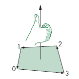
vertex that make up each of the faces. Using the right-hand rule we can
index the vertex in the correct order so that they are pointing to the
correct sequence as shown in the figure below:
Following this we can get the resulting index array:
var indices = [
        0, 1, 1, 2, 2, 3, 3, 0,  // Front
        4, 5, 5, 6, 6, 7, 7, 4,  // Back
        0, 4, 4, 5, 5, 1, 1, 0,  // Left
        3, 2, 2, 6, 6, 7, 7, 3,  // Right
        1, 5, 5, 6, 6, 2, 2, 1,  // Top
        0, 4, 4, 7, 7, 3, 3, 0,  // Bottom
    ];
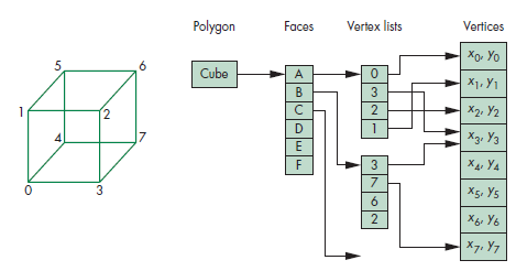
Which follow the vertex-list representation of a cube in accordance to the following figure:
This second form of implementation of a 3D cube has a lot of benefits
including not having to write out all the vertices for each of the
triangles that need to be calculated however you'll notice that this
will only work when drawing the edges, and the color assignation formula
we made for the solid cube will no longer work. Instead we can divide the
vertices into color groups of 4 to show the front and the back of the
cube. It can also be noted that the indices have repetition so they could
be deleted to cut back on drawing time, but for the purposes of this lab
it is good to show how the LINES method renders lines.
We now have to do a transformation to get our cube to the desired
coordinates as specified by the lab and in order to do this we will make
use of what we learned in [[CG Lab 1#Part 4 Rotating a square|Lab 1 Part
4]] in where we rotated a square. However, this time we can specify that
the transformation matrix we will be multiplying our position matrix by is
recognized as the model view matrix which will be part of the Model View
Projection matrix manipulations which go into how the 3D world is
transformed into a 2D projection for the camera. We will discuss this
further in following labs but for a good explanation see this
resource. Going
back we can create our translation matrix using one of the
ML helper method translate or by using the
glMatrix API. We simply need to move the cube to the top
right of the canvas so it's just multiplying the X and
the Y by 0.5. We now have a wireframe cube in
the correct position but it is still being displayed in an orthographic
view. We are asked to view the cube in an isometric view which we can do
by either multiplying our model by the view matrix or by using the helper
method lookAt which takes in as parameters; where the
"eye" or point of view of the camera will be at, the direction
it will be pointing towards, and the "up" direction which
normally would just be a positive Y. This all comes together
for an isometric view as shown in the code below:
var eye = vec3(0.0, 0.0, 0.0);
var at = vec3(1.0, 1.0, 1.0);
var up = vec3(0.0, 1.0, 0.0);
var viewMatrix = lookAt(eye, at, up);
When rendering an object in 3D space the object will appear different at different angles of viewing. For example, a pyramid might look like a flat square to someone looking at it from the bottom up. As such the object must be transformed depending on how the user is looking at it to be rendered on the screen in the correct manner. Currently we are performing this transformation by using the view matrix and multiplying it to the model data. However, this alters the data so whenever we would want to look at the object from a different angle we would have to calculate the new object and view matrices. Instead, we can separate the view matrix into two matrices and implement one as the position and orientation of the camera and the other the projection matrix or how to setup the object in the clipping cube and perspective. We now have three data matrices in total making up our model (the object data), the camera viewing transformation, and the projection/orientation matrix. These three parts make up the model-view-projection format for rendering 3D objects. As such our vertex shader will look like the following:
<script id="vertex-shader-2" type="x-shader/x-vertex">
        attribute vec4 vPosition;
        attribute vec4 vColor;

        varying vec4 fColor;

        uniform mat4 modelMatrix;
        uniform mat4 viewMatrix;
        uniform mat4 projectionMatrix;

        void main() {
            gl_Position = projectionMatrix * modelMatrix * viewMatrix * vPosition;

            fColor = vColor;
        }
</script>
Since our object rendering is now dependent on individual matrices instead
of raw data we can now make new projections of the same object by simply
altering the view and projection matrices. In the previous part we went
over how the view matrix is created using the lookAt method.
In this part we can create the projection matrix which should consist of
the culling cube or the 3D cube around our viewing that we want
to actually render. This culling cube is made up of; how near to
the camera we want data to start rendering and how far we want to
render to. All of this can be normalized to be accepted values of $\pm 1$
for the both how close and how far we want to render to. The projection
matrix must then also take into consideration the screen's aspect
ratio (which can be calculated by dividing the canvas width with the
canvas height) and the camera's FOV (in this exercise we used 45
degrees on the Y-axis). Having this information we can create our
projection matrix using the perspective method included in
the MI framework, as shown below:
var close = 1; // How close the cull point is to the camera
var far = 8; // How far the cull point is from the camera
var fov = 45.0;  // Field-of-view in Y direction angle (in degrees)
var aspect = canvas.width / canvas.height;       // Viewport aspect ratio

var projectionMatrix = perspective(fov, aspect, close, far);
Using our viewing matrix along side our projection matrix means that we now only have to change the viewing matrix to get different perspectives on the same model data. There are three classical ways of viewing 3D objects introduced by the course book that depend on how many of the axis are parallel to the camera. We can mess around with our viewing matrix and present the result below in where the left most cube is projected in a three-point perspective the center is presented in one-point perspective, and lastly the third is presented in a two-point perspective.
This part reflects on the previous part and offers a more concreate look at how the transformations were applied to the cube in order to get the desired results.
For the isometric view: We implemented the model and view matrix into one but basically what was done is the model matrix was multiplied by the view matrix and finally a translation matrix to place it in the correct placement on the screen. Assuming that the camera is at the origin then the cube matrix is found using the formula:
$$ CTM = view \times transformation \times model $$
For the one-point perspective: It follows the same principle as before but now has the FOV and camera projection matrix which is multiplied by the view matrix further multiplied by the model matrix in order to the get the rendering position.
$$ CTM = projection \times view \times model $$ Since the one-point perspective is only looking at one of the axis then the cube does not have to have any special transformation on the model unlike the other point perspectives.
For the two-point perspective: In order to not have our cubes overlap then this perspective along side the three-point perspectives have been translated on the X-axis. The CTM formula remains the same however the view matrices have been altered to match the new desired perspectives. The two-point required the cube to have the x and y axis parallel to the camera so the eye was changed of the view matrix calculation to have the camera start at a different point.
$$ view = \begin{pmatrix} -1.5 & 0 & 6 \ 0 & 0 & 0 \ 0 & 1.0 & 0 \ \end{pmatrix} $$
For the three-point perspective: Again the cube data had to be translated to be displayed at the same time as the other cubes but the projection matrix remained the same only changing the view matrix. This time we need a perspective that shows all three axis at once so we needed to change the view matrix by basically applying a rotation to the cube on the x-axis and the y-axis to show the z-axis. The view matrix used is shown below:
$$ view = \begin{pmatrix} 2 & 1.75 & 6 \ 0 & 0 & 0 \ 0 & 1.0 & 0 \ \end{pmatrix} $$
This part is an optional exercise to demonstrate the techniques learned in this laboratory. It combines the manipulation of the view and perspective matrices in order to show the same cube data in different parts of the screen. The intended result should look similar to that of the figure shown below.
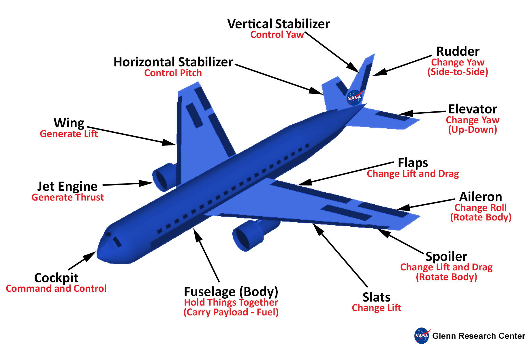
As this was an optional exercise the quality of the plane rendering was not the concern and instead the focus was put on the correct rendering of the cubes in altering the same cube data with the correct view and perspective matrices.
Lab Finished!
Report Finished!
Report Merged!
Optional Tasks Finished!