Part 2: Filtering Modes
The checkerboard is mapped unto the rectangle using nearest neighbor
anti-aliasing and repeat for wrapping modes in the previous part.
However, WebGL allows for different types of texture filtering and
wrapping modes. In this part we will explore the different formats
introduced by the lectures. First we need to setup our testing
environment. Lets add buttons to change the filtering and wrapping
modes. This is done by adding button elements and then changing the
frontend code base like what was done in [[CG Lab 4|Lab 4]]. We will be
using the same checkerboard rectangle from the previous part as a base.
We do change the structure only of the
init method. The last part of the init method
will be where each of the code snippets for the button will be placed.
This makes for easy integration as simply the only thing that needs to
change to update the canvas is to run the render method.
The structure of the init method is shown below:
 // Setup the WebGL environment
canvas = document.getElementById("gl-canvas-2");
gl = WebGLUtils.setupWebGL(canvas);
if (!gl) {
    alert("WebGL is NOT available!");
    return;
}

aspect = canvas.width / canvas.height;

gl.viewport(0, 0, canvas.width, canvas.height);
gl.clearColor(CLEAR_COLOR[0], CLEAR_COLOR[1], CLEAR_COLOR[2], CLEAR_COLOR[3]);

// Drawing parameters
...
//  Load shaders and initialize attribute buffers
...
// Initialize the buffers
var vBuffer ...
var cBuffer ...
// Initialize the texture buffers
var tBuffer ...
// Get the model matrix from the vertex shader variable
uniformLocations = {
    ...
};

// Create the texture
var texture = gl.createTexture();
gl.bindTexture(gl.TEXTURE_2D, texture);

// Set texture parameters
gl.texImage2D(gl.TEXTURE_2D, 0, gl.RGBA, texSize, texSize, 0, gl.RGBA, gl.UNSIGNED_BYTE, myTexels);

// Set the texture in the fragment shader
gl.uniform1i(gl.getUniformLocation(program, "texMap"), 0);

// Set the different texture filtering and wrapping options
// The default options are gl.NEAREST and gl.REPEAT
gl.texParameteri(gl.TEXTURE_2D, gl.TEXTURE_MIN_FILTER, gl.NEAREST);
gl.texParameteri(gl.TEXTURE_2D, gl.TEXTURE_MAG_FILTER, gl.NEAREST);
gl.textParameteri(gl.TEXTURE_2D, gl.TEXTURE_WRAP_S, gl.REPEAT);
gl.textParameteri(gl.TEXTURE_2D, gl.TEXTURE_WRAP_T, gl.REPEAT);

// Buttons for changing the texture filtering and wrapping options
...
Texture Filtering Modes
In this section of the report we will look at how to change the code to accept a button changing the filter mode. This section will also explain the effect of the different filtering modes and their influence on texture magnification minification. As mapping of the texture to the model occurs it is not always a 1-1 direct relationship between the position of the model and the position of the texture. As such, Texture Sampling or otherwise known as Texture Filtering needs to take the decision on what value of the texel to use. The simplest solution is that of taking the closest texture coordinate as the value. This however, leads to a lot of texture aliasing.
Nearest Neighbor Filtering
This is the easiest to start with since it follows the same code as the previous part, all we have to do is add a button that will trigger the following code:
// Nearest button
$("#btn-nearest-4").click(function (e) {
    e.preventDefault();
    gl.texParameteri(gl.TEXTURE_2D, gl.TEXTURE_MIN_FILTER, gl.NEAREST);
    gl.texParameteri(gl.TEXTURE_2D, gl.TEXTURE_MAG_FILTER, gl.NEAREST);
    render();
});
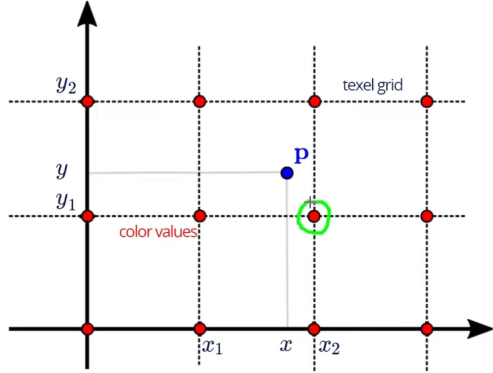
Like Linear Filtering, Nearest Neighbor Filtering uses an interpolation value for the texel from a group on neighbor texel values. Nearest Neighbor is aptly named as when mapping pixels to texels, nearest neighbor chooses the nearest texel value for that corresponding pixel. If we look at the image below we can see that the green highlighted texel value would be chosen for the pixel value $P$.
If the ratio of texels to pixels is larger than 1, meaning that the texels cannot be mapped 1:1 with the model pixels, then a problem occurs that we have more texel data that could be mapped to the model. This is called a minification problem. The opposite can also occur, meaning that we have more pixels than texels, that is called a magnification problem. Linear and nearest neighbor can handle both magnification and minification unlike mipmap which can only handle minification.
Nearest Filtering will result in sharp edges on models but aliasing around the object as some empty values are given an edge value.
Linear Filtering
Adding linear filtering to the code in order to change the texture filtering mode is triggered by an added button and the following code:
// Linear button
$("#btn-linear-4").click(function (e) {
    e.preventDefault();
    gl.texParameteri(gl.TEXTURE_2D, gl.TEXTURE_MIN_FILTER, gl.LINEAR);
    gl.texParameteri(gl.TEXTURE_2D, gl.TEXTURE_MAG_FILTER, gl.LINEAR);
    render();
});
Linear filtering happens when the value for the texel chosen is the weighted average of a group of texels at the point coordinates of the model. Linear filtering has a special case in that since the averages of surrounding texels are taken if the desired point sample is near the edge of the texture then linear filtering will make up values outside the edges to use in the interpolation. Due to linear using interpolation and averaging of texel values some edges will appear blurry as seen in the result. Linear interpolation is done in a bilinear way so that the linear interpolation happens on both directions as shown in the figure below:
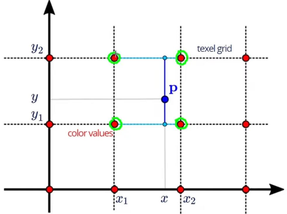
Bilinear interpolation makes sure that the two top texels shown in the image are interpolated to make an average texel $x$ and then the two bottom texels are interpolated to create an average texel $y$. This process makes sure that the interpolated value is an average of all surrounding texel values.
The blurry edges are a result of the ratio between the texels to pixels and are due to the linear progression between pixel values. So in areas where black is meeting white there will be an amount of layers where the blending is transitioning from black to white. The number of layers is driven by the ratio.
This filtering method will result in less sharp images but smoother transition between values.
Mipmap Filtering
Adding Mipmap Filtering to the code in order to change the texture filtering mode is triggered by an added button and the following code:
// Mipmap button
$("#btn-mipmap-4").click(function (e) {
    e.preventDefault();
    gl.texParameteri(
        gl.TEXTURE_2D, gl.TEXTURE_MIN_FILTER,
        gl.LINEAR_MIPMAP_LINEAR);
    gl.texParameteri(gl.TEXTURE_2D, gl.TEXTURE_MAG_FILTER, gl.LINEAR);
    render();
});
Mipmap filtering uses a subdivision technique in where the texture is divided in to lesser and lesser resolutions the deeper the mipmap level it goes. A lot of the time mipmaps are explained visually as a pyramid in where each of the resolution levels indicate a reduction in resolution by half. This can be seen in the image below:
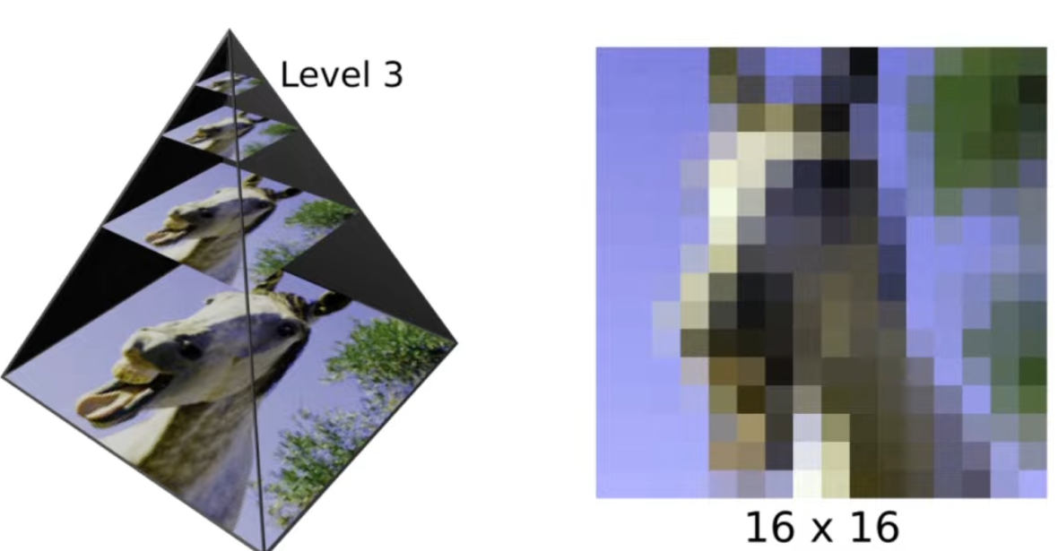
Level 0 is the original texture image and if we take for example, a level 0 texture image of resolution $128 x 128$ then at level 1 the texture resolution will be $64 x 64$, and level 3 the texture resolution will be $16x16$ as shown in the image above. Mipmapping is used to minimize the minification that could occur in order to get a ratio of 1 texel to 1 pixel. This is done by the GPU going up the pyramid and calculating the ratio and choosing to sample from the layer that gets close to 1:1. There is also the choice to interpolate a value between two layers in a trilinear interpolation manner for smoother results.
Mipmapping filtering results in smoother images especially in images that have high levels of noise. We can see this in our result on the upperparts of the checkerboard, this is due to the value farther away from the image resulting in low texel to pixel values and thus the GPU using mipmaps to generate smoother results. Mipmaps do nothing if the ratio is higher than 1 and thus in the lower parts of the checkerboard the results not changed from the original.
Texture Wrapping Modes
This section of the report will look at how to change the code to accept a button changing the texture wrapping mode. Wrapping occurs when the model is larger than the texture size as the GPU will make the decision to cover the rest of the model with the texture. This section will look into how two modes handle this problem.
Repeat Wrapping
Adding Repeat Wrapping to the code in order to change the texture wrapping mode is triggered by an added button and the following code:
// Repeat button
$("#btn-repeat-4").click(function (e) {
    e.preventDefault();
    gl.textParameteri(gl.TEXTURE_2D, gl.TEXTURE_WRAP_S, gl.REPEAT);
    gl.textParameteri(gl.TEXTURE_2D, gl.TEXTURE_WRAP_T, gl.REPEAT);
    render();
});
Repeat wrapping handles the larger model by simply repeating the texture until it covers the entire model. There is a spin on the repeat function called "repeat mirrored" which will mirror the texture on the next iteration. Repeat wrapping is useful to cover the entire model with texture but can result in a tile look.
Clamp-to-Edge Wrapping
Adding Camp-to-Edge Wrapping to the code in order to change the texture wrapping mode is triggered by an added button and the following code:
// clamp-to-edge button
$("#btn-clamp-4").click(function (e) {
    e.preventDefault();
    gl.textParameteri(gl.TEXTURE_2D, gl.TEXTURE_WRAP_S, gl.CLAMP_TO_EDGE);
    gl.textParameteri(gl.TEXTURE_2D, gl.TEXTURE_WRAP_T, gl.CLAMP_TO_EDGE);
    render();
});
Clamp-to-Edge wrapping covers the model with the last value of the texture. This is made obvious in the result at the edges. This has trouble areas such as the corner of the model in where entire areas are given the same value. This form of wrapping is not the same as texture stretching as the texture is not interpolated in any way.