The purpose of this set of exercises is to get started with WebGL. You will setup a WebGL application from scratch, create a canvas and a WebGL context, compile and use simplistic shader programs, setup the needed buffers for drawing, and draw and animate simple shapes.
Tasks:
This part of the lab is all about setting up the canvas and the workspace. Here we use the foundation setup for
the HTML suggested by the book in where there is an canvas element and the import of the dependencies. The
naming convention for the canvas' ID will be gl-canvas-# where # represent the
part number. The JavaScript is not setup as suggested by the book however, as there are multiple canvases on the
webpage for that lab exercise. As such, the render helper method will not be used and instead the color buffer
clearing and the drawing of the data arrays must be done within one of the methods for that part. This will
separate each of the code for the part inside it's own method named respectively, part# where
# represents the part number written out in words (i.e. partOne for part 1).
Setting up the canvas in JavaScript is done by getting the HTML canvas element from the DOM by using the
document.getElementById method. Once the canvas is retrieved that can be used to setup the WebGL
context by using one of the WebGLUtils called setupWebGL. Here we can assign the WebGL
context to a JavaScript variable and checking if it was assigned to report an error to the user if the
WebGLUtils could not be used. This can be seen in the code below:
var canvas = document.getElementById("gl-canvas-1");
var gl = WebGLUtils.setupWebGL(canvas);
if(!gl){
    alert("WebGL isn't available!");
}
If the environment context was setup successfully then we can continue setting up the canvas by choosing the
viewport size and the background color. This is done by using the viewport and
clearColor methods respectively. The viewport method takes x/y coordinates which
represent where the origin of the viewport should be (default 0), and it takes a width and height specifying the
size of the viewport. For most the course I suspect it will be the entire canvas. The clearColor
method specifies what color values the buffer will use when calling the clear method. This method
simply takes a RGBA value. For Part 1 we were required to use the Cornflower Blue color for the clear color and
make the canvas 512 pixels which was done in the HTML already, so we just need to make the canvas the size of
the HTML element, and for the color applying we just need to clear the color buffer, all together the code is
shown below:
    gl.viewport(0, 0, canvas.width, canvas.height);
    gl.clearColor(0.3921, 0.5843, 0.9294, 1.0); // Cornflower blue
    gl.clear(gl.COLOR_BUFFER_BIT);
For part 2 we continue working with the setup of the first canvas we now however need to draw three points unto the canvas. This is done by placing the coordinates of the points unto the GPU buffer which in turn requires the use of a vertex and fragment shader. First we can create our data making up the points by indicating where those vertices for the points are. This is done using 2D vectors as shown below:
var points = [
    vec2(0,0),
    vec2(1,0),
    vec2(1,1)
]
We need to create and initialize a GPU buffer in order to place the data unto the GPU. We use the WebGL methods
createBuffer to register the buffer space and we use the bindBuffer method to bind
that register to the buffer. The bindBuffer takes a binding takes the target, or the specifying
buffer binding point (in our case we are using the ARRAY_BUFFER which binds the data to vertex
attributes). This is done by the code:
var bufferId = gl.createBuffer();
gl.bindBuffer(gl.ARRAY_BUFFER, bufferId);
We can now use the bufferData method in order to place the data unto the GPU buffer. This method
takes the target, the data (the book uses the JS method flatten to place the data in order), and
the usage which is the intended pattern of the data store for optimization purposes (in our case we use
STATIC_DRAW to show that we intend to specify this data once). Overall, the code for placing the
point data on the GPU is:
gl.bufferData(gl.ARRAY_BUFFER, flatten(points), gl.STATIC_DRAW);
Now that we have a GPU data buffer we need to have a WebGL program to interpret the data, for this we use the book's simple vertex and fragment shaders:
<script id="vertex-shader" type="x-shader/x-vertex">
        attribute vec4 vPosition;

        void main() {
            gl_PointSize = 20.0;
            gl_Position = vPosition;
        }
</script>

<script id="fragment-shader" type="x-shader/x-fragment">
        precision mediump float;

        void main() {
            gl_FragColor = vec4( 1.0, 0.0, 0.0, 1.0 );
        }
</script>
The vertex shader also specifies what size the data points on the GPU will be which the laboratory asked for
pixel size of 20. We also, change the fragment color so that it is more visible against the cornflower blue.
Using the above shaders we can initialize or WebGL program by using the initShaders and the
useProgram methods of WebGL. The initShaders method simply takes a WebGL context with
the vertex shader and the fragment shader scripts. Shown below:
var program = initShaders(gl, "vertex-shader", "fragment-shader");
gl.useProgram(program);
Now that we have a data buffer and shaders we need to associate the two by stating where the viewport is on the
webpage so that the GPU can render correctly. This is done by using the JS method getAttribute. We
then assign this vertical position to the the ARRAY_BUFFER by using the
vertexAttribPointer method which takes, the index of the vertex attribute that is to be modified,
the size of components per vertex attribute, the data type of each component, the offset of bytes between the
attributes, and the offset in bytes of the first attribute. We can then turn on the generic vertex attribute
array by specifying the index of where it is using the method enableVertexAttribArray. The
association of the buffer and shaders is shown below:
var vPosition = gl.getAttribLocation(program, "vPosition");
gl.vertexAttribPointer(vPosition, 2, gl.FLOAT, false, 0, 0);
gl.enableVertexAttribArray(vPosition);
Now we just need to clear the color buffer and draw the arrays of the points using the drawArrays
method which we will need to specify the method on how to draw it such as :
gl.POINTS: Draws a single dot.gl.LINE_STRIP: Draws a straight line to the next vertex.gl.LINE_LOOP: Draws a straight line to the next vertex, and connects the last vertex back to
the
first.gl.LINES: Draws a line between a pair of vertices.gl.TRIANGLE_STRIPgl.TRIANGLE_FANgl.TRIANGLES: Draws a triangle for a group of three verticesThe code for which is:
gl.drawArrays(gl.POINTS, 0, points.length);
In order to change the points into a triangle we have to change the last step in the previous part and change the
way
that WebGL is drawing the data. Previously we specified to draw a single dot now we can use the same
drawArrays method but now specified to draw triangles ,which will draw a triangle for every group
of
three vertices. The code will be:
gl.drawArrays(gl.TRIANGLES, 0, points.length);
As for adding a second color buffer we can do that by adding a second attribute to the vertex shader. Since we
are
using a different vertex shader we have to differ from the format suggested by the book and instead simply add a
new
HTML script under each of the canvases following the naming convention of vertex-shader-# and
fragment-shader-# for each of the different parts.
Essentially our application so far follows the following steps:
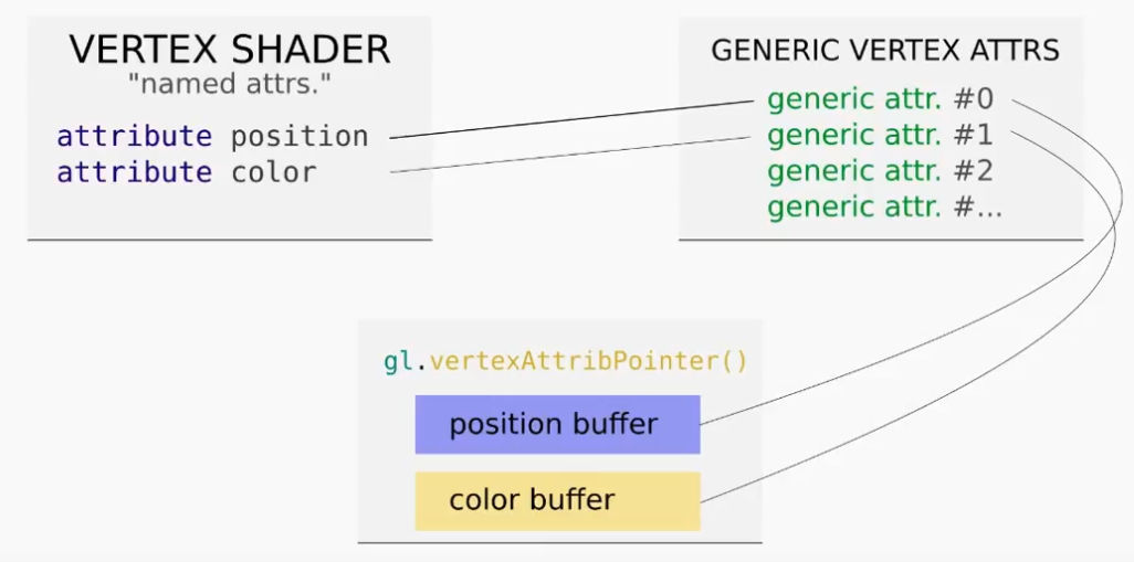
In order to add a new color buffer a color attribute needs to be added to the vertex shader which can be done by adding a new generic vertex attribute array. Essentially this means we need to change step 4 and step 6 in the above steps. To add an attribute you need to also map that generic vertex attribute to the pointer in a buffer. This essentially means whenever you are adding an attribute you are changing three linked parts as shown below:
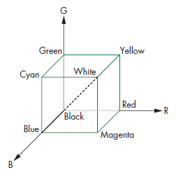
So first list create the color data that we want to buffer to the GPU by remembering how colors are represented in computers. Colors are represented by a RGB vector in where each of the axis are Red, Green, and Blue respectively. We then normalize each of these vectors to 1 being the highest magnitude which visually can be represented in the figure below:
Using this color grid we can then create our data as so:
const colorData = [
        vec3(1, 0, 0),
        vec3(0, 1, 0),
        vec3(0, 0, 1)
    ];
With our data created we can now go ahead and create our color buffer and placing the data unto the GPU just like before with the point data:
const colorBuffer = gl.createBuffer();
gl.bufferData(gl.ARRAY_BUFFER, flatten(colorData), gl.STATIC_DRAW);
We can now alter the vertex and fragment shaders in order to have this new color attribute. Keep in mind that we have declared a pixel color in our previous fragment shader, however, the way that WebGL specifies color is not by pixels but by vertex, making the developer's life easier. Here we can now use a varying variable in order to pass the vector color buffer between the fragment and vertex shader as shown in the code below:
<script id="vertex-shader-3" type="x-shader/x-vertex">
        attribute vec4 vPosition;
        attribute vec3 color;

        varying vec3 vColor;

        void main() {
            gl_Position = vPosition;

           // Set the attribute to the varying variable to be used in the fragment shader
            vColor = color;
        }
</script>
<script id="fragment-shader-3" type="x-shader/x-fragment">
        precision mediump float;

        varying vec3 vColor;

        void main() {
            gl_FragColor = vec4(vColor, 1.0);
        }
</script>
Now that the shaders are setup we have to map the attributes to the buffers using the pointers. When using
vertexAttribPointer it is important to note that the way the method checks which buffer is being
pointed towards is by taking the most recently bound buffer. This means that we have to re bind the buffers
before
calling the method or else we will be pointing to the same buffer for the position and the color buffer.
var colorLocation = gl.getAttribLocation(program, "color");
    gl.enableVertexAttribArray(colorLocation);
    gl.bindBuffer(gl.ARRAY_BUFFER, colorBuffer);
    gl.vertexAttribPointer(colorLocation, 2, gl.FLOAT, false, 0, 0);
Since we are already drawing triangles as our draw method, which takes every three vertices and draws a triangle, we simply have to add another 3 vertices to our data in order to draw a square. This is done by simply adding 3 more vertices to the data:
var data = [
// The first triangle
    vec2(0, 0),
    vec2(1, 0),
    vec2(1, 1),

// The second triangle
    vec2(0, 0),
    vec2(0, 1),
    vec2(1, 1)
];
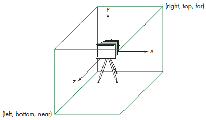
To translate the square to the center of the screen we have to understand that WebGL is rendered using a orthographic view of the data cube defined by the planes, x=\pm1 , y=\pm1 , and z=\pm1 as shown in the picture below:
In our case we want the center of the square to translate from the top right of the screen (like the triangle was drawn in the previous parts) to be at the value of the 0 in the x and y axis. This can be done by doing some matrix multiplication to translate the data. We know in our situation that we want to move the coordinates by 0.5 to the left so we can subtract that to each element of our data. JavaScript does not come with built in functions to manipulate matrices but a simple way is to iterate through each of the elements using a loop we see a lot in computer science:
for (var x = 0; x < data.length; x++) {
        for (var y = 0; y < data[x].length; y++) {
            data[x][y] = data[x][y] - 0.5;
        }
}
From the above loop we can now see how resource intensive this would be for the CPU to handle every time we would
want to translate an object say in an animation. If we have 1000 squares we want to move or dare say cubes the
calls
will pile up quick, hence the existence of a GPU. In this next task we will be doing the animations on the GPU
instead which is done inside our vertex shader. In [[CG Lab 1#Part 3|Part 3]] we saw how attributes are used to
send
data to the GPU however, these attributes are not permanent and can differ for each vertex. As such, we now use
a
WebGL variable called uniform.
We also are asked to rotate our matrix which is done by multiplication of each of the points by a rotation matrix seen below in where: $$\theta = \frac{\pi}{4}$$ :
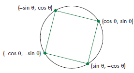
$$ \begin{pmatrix} x \ y \end{pmatrix} \begin{pmatrix} cos\theta & sin\theta \ -sin\theta & cos\theta \end{pmatrix} $$ We can do these calculation on the GPU directly so that we are not wasting time sending data to and from the CPU and at the same time making our rotation of the square easier to be done in the future by setting up the square to be in a point in space where each of the vertices correspond to the following figure:
We again use a uniform variable for the transformation matrix and using the following code in the vertex shader we determine the position based on that angle:
attribute vec4 vPosition;
uniform float theta;

void main() {
gl_Position.x = -sin(theta) * vPosition.x + cos(theta) * vPosition.y;
gl_Position.y = sin(theta) * vPosition.y + cos(theta) * vPosition.x;
gl_Position.z = 0.0;
gl_Position.w = 1.0;
}
Or instead since the GL shading language was invented for the purpose of graphics you can multiply matrices and
vectors which we can use our rotation matrix, which is what was done for this lab but keep in mind that the
course
book suggests the above code format. To feed the values you use the getUniformLocation which works
the
same way as getAttributeLocation . The code however makes sure that all the
uniformaLocations are in the same object and later the attributeLocations should be in
an
array as well. For the solution for this task the gl-matrix library was used to easily make the
transformation matrix need to be multiplied to the data. The code will be then:
    // Declaration of the uniform variables
    var uniformLocations = {
        tMatrix: gl.getUniformLocation(program, "tMatrix"),
    };

    // Create the transformation matrix using the gl-matrix library
    var tMatrix = glMatrix.mat4.create();

    // Rotate the triangle by 45 degrees in radians
    glMatrix.mat4.rotateZ(tMatrix, tMatrix, (Math.PI / 4));
Make sure that when applying transformations they are applied in reverse order
    that they are declared in the code!
Now we can work on the last task of the lab which is the animation of constant rotation. This is done using the
requestAnimationFrame method which takes in a function to call once the animation is done. We can
therefore call the method inside the function it will call to loop the animation forever. Inside the function we
can
then call the drawArrays method to update the GPU with the new rotation, we must keep in mind that
whenever you call the GPU to do something it will overwrite everything from before so we also need to clear the
screen to get the background and we need to update the uniform variable for the next animation call. The code
can be
seen below:
    // The animation function called by the CPU
    function animate() {
        requestAnimationFrame(animate);

        // Clear the canvas
        gl.clear(gl.COLOR_BUFFER_BIT);

        glMatrix.mat4.rotateZ(tMatrix, tMatrix, (Math.PI / 4) / 100);

        // Update the value in the GPU
        gl.uniformMatrix4fv(uniformLocations.tMatrix, false, tMatrix);

        // Draw the data on the GPU
        gl.drawArrays(gl.TRIANGLES, 0, data.length);
    }
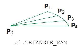
For this part of the lab we will understand how to properly draw a circle using the gl.TRIANGLE_FAN
drawing method. The way that this method works is that the first vertex is used as the origin vertex in where
the
next two vertices in the data will form a triangle. Every subsequent pair of vertices will therefore draw a new
triangle based on the origin vertex as highlighted in the figure below:
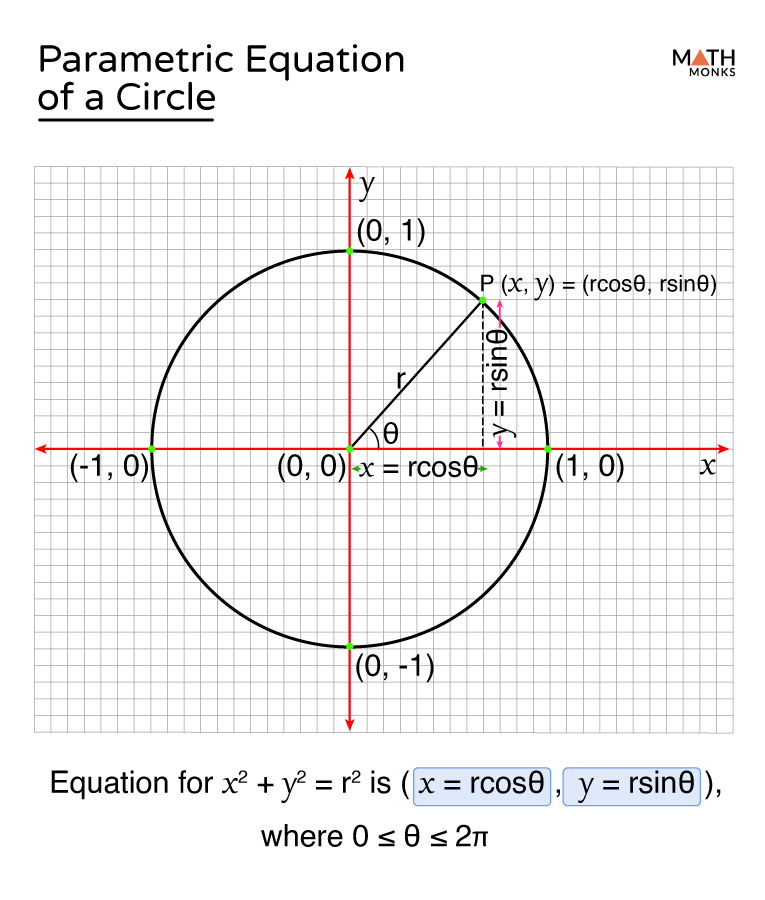
To draw a circle we would just need to specify vertices around an origin, depending on how many vertices we specify the circle will appear more detailed or less detailed. Doing a bunch of estimations for the vertices is not ideal instead we can codify this such that we find a vertex coordinate from a 360 arc. This comes from remembering the parametric equation of a circle as shown in the picture below we can multiply our radius (since the lab does not specify we can decide the radius) and multiply it; by cos theta to get our x value, or by sin theta to get our y.
The resulting code to draw a circle using the TRIANGLE_FAN drawing method is as follows:
    const RADIUS = 0.5;

    var vertices = [];

    // This could be 3D just by adding a 3rd vertex to the coordinates below
    var vertCount = 2;

    // Loop 360 degrees to create a circle
    for (var i = 0.0; i <= 360; i++) {
        // Convert degrees to radians
        var j = i * Math.PI / 180;

        // Get X and Y coordinates
        var vertex = [
            (Math.sin(j) * RADIUS),
            (Math.cos(j) * RADIUS),
            // Add another dimension for 3D
        ];
        vertices = vertices.concat(vertex);
    }
    var dataSize = vertices.length / vertCount;

    // Draw the data on the GPU
    gl.drawArrays(gl.TRIANGLE_FAN, 0, dataSize);
The last task in this lab is to animate the circle being translate up and down the canvas. To do this task we can
use
the same principle of using the requestAnimationFrame method for animating the ball falling.
However,
we need to prevent the ball from going off screen and then switch to animating the ball going back up. Later in
the
course we will understand how to check if a pixel has gone off the viewport but for now we will simply implement
this manually by trial and error. The way the code works is that the CPU will use the
requestAnimationFrame a certain count of times and then instead of calling itself it will then call
a
different method that holds a transformation matrix not for a -y translation but for a positive y
translation
and vice versa.
 const FRAME_TIME = 20;
 const MAX_COUNT = 48;

 var count = 0;

 animateDown();

 // The animation function called by the CPU
    function animateUp() {

        setTimeout(function () {
            if (count <= MAX_COUNT) {
                requestAnimationFrame(animateUp);
                count++;
            } else {
                count = 0;
                requestAnimationFrame(animateDown);
            }

            // Clear the canvas
            gl.clear(gl.COLOR_BUFFER_BIT);

            // Translate the ball up by adding 0.1 on the y-axis
            glMatrix.mat4.translate(tMatrix, tMatrix, [0, 0.01, 0]);

            // Update the value in the GPU
            gl.uniformMatrix4fv(uniformLocations.tMatrix, false, tMatrix);

            // Draw the data on the GPU
            gl.drawArrays(gl.TRIANGLE_FAN, 0, dataSize);

        }, FRAME_TIME);
    }

    function animateDown() {
        setTimeout(function () {
            if (count <= MAX_COUNT) {
                requestAnimationFrame(animateDown);
                count++;
            } else {
                count = 0;
                requestAnimationFrame(animateUp);
            }

            // Clear the canvas
            gl.clear(gl.COLOR_BUFFER_BIT);

            // Translate the ball down by subtracting 0.1 on the y-axis
            glMatrix.mat4.translate(tMatrix, tMatrix, [0, -0.01, 0]);

            // Update the value in the GPU
            gl.uniformMatrix4fv(uniformLocations.tMatrix, false, tMatrix);

            // Draw the data on the GPU
            gl.drawArrays(gl.TRIANGLE_FAN, 0, dataSize);

        }, FRAME_TIME);
    }
Lab Finished!
Report Finished!
Report Merged!